Power Plant Water: Wanted Dead AND Alive
Published on by Jim Lauria, VP Sales & Marketing at Mazzei Injector Company, LLC in Technology
Water is the lifeblood of electrical power plants, whether they are water-cooled steam plants or turbine-spinning hydroelectric installations.
Regardless of how the facility generates electricity, there is a growing awareness that each power plant is part of its own, unique industrial watershed—drawing water from the environment, altering its contents and temperature, releasing some to the atmosphere as steam, and returning the rest to receiving waters.
That is a deep responsibility, and awareness of it is pushing the issue of dissolved oxygen (DO) to the surface in many conversations about water treatment at power plants. In the power plants themselves, oxygen in the water accelerates corrosion of equipment- DO is thus aggressively minimized. However, as water is returned to nature, DO must be renewed and replaced to prevent harm to the aquatic ecosystem and to meet regulations set by local and national environmental agencies.
Two key factors add dramatically to the impact of power plants on DO in their respective watersheds: the sheer volume of water that the facilities withdraw and return, and the temperature at which water is reintroduced to the environment. A massive flush of low-oxygen water can have huge negative impacts on DO in receiving waters simply due to the sheer volume. Temperature impacts both the physics and biology of DO―physically, warm water is not capable of holding as much oxygen as cool water is. From a biological perspective, DO uptake can double with an increase in temperature of 10 degrees Celsius, according to the Electric Power Research Institute (EPRI).
Reducing Withdrawals
The bottom line remains that power plant operators are anxious to efficiently increase DO levels in the water they return to their watersheds, and federal regulations keep the pressure on.
One key step is minimizing the amount of water withdrawn and returned to rivers, streams and aquifers. Recirculating systems, first instituted in the 1970s, have had a dramatic impact on reducing water withdrawals for power plant cooling systems. According to a 2008 report by the Union of Concerned Scientists, freshwater withdrawal intensity in Virginia, North Carolina, Michigan and Missouri—where once-through cooling systems are the norm—were 41 to 55 times greater than in Utah, Nevada and California, which boast more recirculating systems.
Further improving water efficiency, nearly 25 percent of the water utilities that serve power plants are implementing non-potable re-use programs, channeling recycled water to cooling towers, according to Black and Veatch’s 2016 Strategic Directions Water Industry Report. The engineering company expects that number to double in the next three years.
Oxygen: The Key Component
Many of the pollutants that can make industrial wastewater discharge a challenge—nutrients, sediment and metals—are typically removed from cooling water before use to protect cooling systems from buildup of contaminants, minerals, scale and slime. As mentioned earlier, dissolved oxygen is also removed to reduce corrosion of equipment in the plant. Whatever little DO remains in the water is depleted in the heating and cooling process at steam generating plants, and can be altered chemically and biologically in the reservoirs at hydroelectric plants. As a result, the fundamental concern in cooling water that will be discharged back into the environment by power plant operators is typically low to no dissolved oxygen.
Over the years, designers of power plants and hydroelectric facilities have utilized a wide range of technologies to reintroduce dissolved oxygen to water before it is returned to the environment.
Some, like weirs that rely on cascades of falling water to incorporate air into the flow, are low in energy demand but require a lot of space and are also limited by flow rates. Others, like surface aeration or mixing rotors, are energy-intensive, high-maintenance and low-efficiency. Diffused aeration systems seem effective at first blush, but despite the satisfying vision of millions of bubbles in the water, their gas transfer efficiency rarely exceeds the 15-to-25-percent range. Speece cones inject pure oxygen into a sidestream flow, but are expensive and inflexible, useful only in open reservoirs.
Venturi Injectors
Venturi injectors have been proven to be extremely efficient and reliable for increasing DO levels in a wide range of applications ranging from industrial wastewater lagoons to winemaking. The unique shape of a Venturi injector uses the flow of liquid to draw in air or oxygen and mix it with the stream, shearing the bubbles to instantaneously transfer high levels of gas into solution.
In power plants and other industrial applications, a boosted sidestream passed through a Venturi injector is reintegrated into the main flow in a Pipeline Flash Reactor (PFR). In a PFR, a length of pipe serves as an inline mixing zone in which carefully designed nozzles further shear entrained gases as aerated water is returned to the main flow, maximizing the gas/liquid interface and transferring gas quickly and efficiently, with no break in pipeline pressure.
In the Field
A Texas power plant discharging 1.5 to 3 MGD of cooling tower effluent installed a sidestream Venturi injection system and a 3.5-foot PFR to increase DO levels. Untreated water, with DO ranging from 0 to 3 mg/L depending on the season, is pumped two miles from the plant’s cooling tower to the settling pond, then another three-quarters of a mile to the point of discharge at a local creek. State regulators mandated that the operator increase DO levels to a minimum of 5 mg/L prior to discharge; the water is tested weekly for compliance.
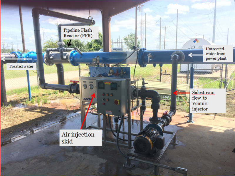
A sidestream Venturi injection and PFR system—small enough to fit on a single, 30-square-foot pallet—was installed immediately prior to the discharge point. This system requires minimal maintenance - the only equipment with moving parts is the small sidestream pump.
Weekly sampling showed the system raised DO in the water to the 8 ppm levels requested by the plant managers—well above minimum mandated levels.
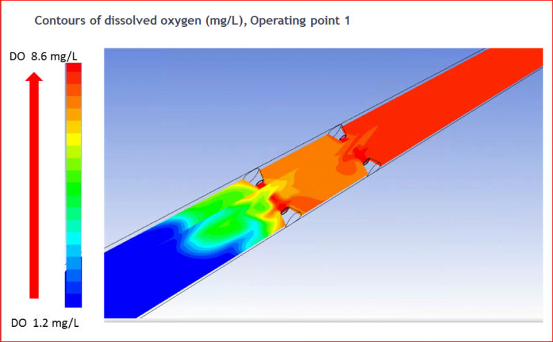
Dr. Srikanth Pathapati, director of computational fluid dynamics (CFD) analysis for Mazzei Injector Company, explains that thorough modeling of the injector and PFR system allow designers to optimize the size and layout of the flash reactor’s nozzles. Careful CFD analysis can be used to ensure confident compliance with regulations. In the power plant’s case, CFD analysis ensured the construction of a highly efficient injector/PFR system and modeled its effectiveness with a high level of accuracy, predicting an output of 8.6 ppm DO where the sampled DO turned out to be 8.8 ppm for one operating point, and 7.2 ppm DO where the sampled DO was 7.15 ppm for a second operating point.
With a small, highly efficient sidestream Venturi injector and Pipeline Flash Reactor system, the Texas utility better integrated itself into its industrial watershed—without additional ponds, tanks, weirs or agitators and with a negligible increase in energy expenditure.

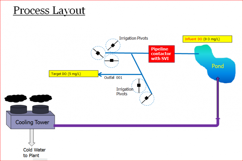
A Texas power plant pipes wastewater from its cooling tower 2 miles to a settling pond. Its discharge permit requires dissolved oxygen levels to be increased to 5 mg/L before it is pumped to irrigation pivots or released into a river. The oxygen is added with a skid-mounted Venturi injector and a Pipeline Flash Reactor (PFR).

Close to the discharge point, a sidestream of power plant cooling tower effluent is run through a Venturi injector, drawing in air, and then reinjected to the main flow through a Pipeline Flash Reactor. The skid-mounted system increases dissolved oxygen from 0-3 mg/L to 5 mg/L in just a few feet. The only moving parts are in the small sidestream pump.

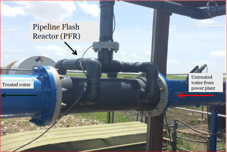
A Mazzei Pipeline Flash Reactor (PFR)—just 3.5 feet in length—injects aerated sidestream water into the main flow through carefully sized and positioned nozzles to maximize gas transfer.

Computational fluid dynamics (CFD) plays a vital role in designing Venturi injectors and Pipeline Flash Reactors (PFR). Every angle and every nozzle position must be optimized for maximum efficiency. In this CFD diagram of a PFR, low-oxygen water (blue and green) passes through nozzles introducing aerated sidestream water, uniformly elevating dissolved oxygen levels (red) in the main flow almost instantly.
Media
Taxonomy
- Water
- Cooling Systems
- Energy
- Energy
- Power Plants
- Cooling
- Hydro Power Planning