Secondary Containment to Help Enable Use of Chlorine Gas for Chlorination
Published on by Jordan Wallis, Marketing Coordinator at ChlorTainer in Case Studies
Veteran Potable Water Superintendent Sees Benefits of Secondary Containment Equipment to Help Enable Use of Chlorine Gas for Chlorination
by Cliff Lebowitz
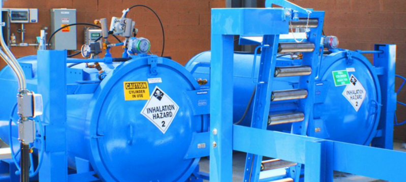
Arsenic Treatment Facility (Image by ChlorTainer )
A veteran potable water production and treatment superintendent, currently overseeing potable water needs for a federal reservation, reports significant benefit from the availability of secondary containment equipment for chlorine gas storage, as part of a management strategy to help enable the use of that chlorination method. He needs chlorine for oxidation in four arsenic treatment facilities (ATF’s), as well as for direct chlorination of well water for reservoir deposit, at two other locations. In his previous superintendent job, he had achieved chlorination by making bleach from tablets, which was a much more troublesome method.
“Special secondary containment units for chlorine gas cylinders were originally installed before I started this job, and I’ve seen how they helped enable the use of chlorine gas,” said the superintendent. His six potable water production facilities serve a residential population of about 2,000, plus a transient commercial demand from another 10,000 users.
“At my last job, which was a similar position for a municipality, we were unaware of the opportunity to use this containment equipment to enhance the gas option. To meet our chlorination needs, we used tablet feeders to make bleach, by eroding the tablets into a solution tank. That was the method we chose as an alternative to needing a scrubber available to neutralize any chlorine gas that might escape cylinders during delivery, change operations, or storage.”
“Those tablet feeders turned out to be an expensive and very high maintenance method,” he continued.
“The tablets would often bridge inside the hopper, stopping the bleach production, and ending the chlorine feed we needed. We would have to dump the bridged product, absorbing that cost, and clean out the hopper, adding an unwanted task to our maintenance time.”
“In addition, the feed pumps would either plug up or burn out all the time, because calcium would build up inside them. They had to be pulled and acid washed, adding further costs and maintenance. I also tried salt generation units, but the rock salt would also bridge, and electrodes that were needed for the process would frequently burn up, costing $5,000 per replacement.” He noted that the tablet method also created an operations burden.
“We had to constantly adjust the feed units to keep the 1 ppm (1 mg/L) chlorine residual we needed. With the gas system in place here, the residual stays where we need it much more consistently. We just have to adjust it seasonally, when we need higher residuals in the summer, and we don’t have to touch it again until the ambient temperatures come back down.”
The ChlorTainer™ cylinder containment vessels, supplied with loaders, scale systems, and instrumentation, were manufactured by TGO Technologies of Santa Rosa, CA.
“I’ve been surprised at how easy it has been to use the cylinder containment equipment,” he added.
“It’s pretty much worry-free. We haven’t had any cylinders leak into the containment vessel yet, but it’s still good to have the added safety, with chlorine storage located near population centers. And whenever we’ve needed to make a phone call in the last four years for service or spare parts, the manufacturer has jumped to it real quick.”
“If we did get a leak, we wouldn’t lose any product, because it would still be fed off the pressure containment vessel; we would just move the vacuum regulator to another valve, and continue to feed, pretty much without interruption. If we had to neutralize escaped gas in a scrubber system, it would be wasted chlorine, and you would have to rehab your scrubber, as extra absorbed costs.”
Water Production Facilities
The superintendent oversees the water production and treatment for four arsenic treatment facilities (ATF’s), with output ranging from one to four MGD, and all receiving raw water from wells. Chlorine gas is fed at 30-50 lbs/day for the oxidation part of the process for well water that is coming in at 1200-1600 gpm. The process continues with coagulation and filtration, with the desired 1 ppm (1 mg/L) residual needed by the time the arsenic is removed. The chlorine gas is injected into the filter influent header, along with ferric chloride (FeCl).
Two other treatment facilities, seeing 400-600 gpm from the wells, use granular iron media to remove the arsenic through adsorption. Chlorine is added at about 5 lbs./day as post-disinfection, to get the 1 ppm (1 mg/L) residual needed for subsequent reservoir storage.
Chlorine Gas Secondary Containment Equipment
Emergency response plans are in place, and risk management plans (RMP’s) are in progress, for each chlorine gas storage location. The secondary containment vessels’ scales connect to the facility’s supervisory control and data acquisition (SCADA) system. The original containment systems units were replaced with more advanced models when they were developed by the manufacturer.
Each of two ATF’s has two 1-ton Chlortainer units, with one online and the other serving as a backup. When a cylinder switches over, a replacement is ordered for the empty. Any 1-ton cylinder with chlorine in it is always in a Chlortainer. Risk management is concerned with best procedures for receiving full cylinders and swapping them out.
At the reservoir facilities, each has three 150-lb. Chlortainer units, with each holding two cylinders, and both feeding simultaneously. The three units are installed where chlorine-treated well water goes to the reservoir. Wells operate off the reservoir level.
All storage sites are checked daily by a technician, who monitors residual levels to see if any feed rate adjustment is needed and also checks the units’ vacuum regulators.
“You have a really good idea of when a cylinder is going to run empty by monitoring the Chlortainer weight scales,” the superintendent noted.
The containment systems were simply positioned on concrete pads and bolted down. A nitrogen-powered fail safe valve and leak detection unit shut down the system if there is a leak detected from the containment vessel.
The vessels are designed for not less than 40 years of service. They enclose chlorine gas cylinders, the chlorine transfer hose, and seismic lock-down brackets.
The chlorine transfer hose is attached to the supply valve, pressurized, and tested for any leaks at the hose ends. Then the door is closed, and secured by a clamshell locking mechanism.
Operators switch to the standby containment vessel automatically when the full cylinder runs empty, opening the vacuum breaker valve. The switch-over is performed automatically and does not require personnel to be present.
With any accidental leaks of chlorine kept within the containment vessel, no atmospheric venting is generated. The vessels are ASME-rated pressure tanks, and any leaks are recycled to the injection system at a normal flow rate. A failsafe valve ties into the chlorine leak detection sensor, so that in the event of an external release, the nitrogen failsafe valve will close, stopping any external leak.
To test for leaks within the containment vessel, there are valved ports that can be opened for testing for chlorine gas. If a leak is discovered within the containment vessel, the operator can withdraw the chlorine gas through a vacuum line that delivers the gas into the treatment process. Thus, chlorine gas leaks are not only contained within the containment vessel, but the gas can also be extracted, and delivered via the typical chlorine feed system.
Any leak or release of chlorine gas from the vacuum line downstream of a vacuum regulator will lose the vacuum condition and cause the vacuum regulator to close, stopping the flow of chlorine gas to the vacuum line. The maximum release of chlorine gas will be the amount of chlorine gas that is the length of the vacuum line to the chlorine injector, and not drawn into the water solution by the suction of the injector.
There can be a question of the integrity of the system from the outlet line, where chlorine gas penetrates the wall of the pressure vessel, to the location where the vacuum line leaves the outlet side of the pressure regulator. A study has shown this could release less than 0.0009 lbs. of chlorine gas. Should there be a gas leak inside a ChlorTainer™ vessel, there is no waste, as the gas is processed at a normal rate until everything is used.
*Cliff Lebowitz heads Catalytic Reporting, LLC, which specializes in third-party case history reporting for industrial equipment manufacturers. Reporting is based on interviews of end users and is approved by them for accuracy and completeness.
Attached link
https://chlortainer.com/Media
Taxonomy
- Industrial Equipment
- Oil & Gas
- Water
- Public Health
- Treatment
- Policy
- Technology
- Environment
- Energy
- Water Supply
- Infrastructure
- Project planning and scheduling
- Risk Management
- Project Management