Actual Velocity in Sewer vs Design Velocity by Manning's Equation
Published on by Yongseok Choi, Senior Manager at GS E&C in Technology
I have a question about the actual velocity in the sewer, especially stormwater pipe.
In many cases, people calculate the design velocity using Manning's equation and I've seen a lot of people calculate the velocity over 3.0 m/s or even more than 12 m/s according to the pipe slope.
They have calculated the velocity based on the assumption that water flows full in the pipe, but I think water does not flow full in the pipe in most cases.
Design guideline states the design velocity shall not exceed 3 m/sec. The acceleration of gravity in the vacuum condition is just 9.8 m/s2, so it's not possible for the design velocity to exceed 9.8 m/s. I've heard the terminal velocity of rain drop is about 2 m/s.
Is there anyone who has data or experience with actual and design velocity in the sewer under gravity?
Taxonomy
- Sewage Treatment
- Storm Water Management
- Infrastructure Management
- Advanced Metering Infrastructure
- Sewer Networks
- Hydraulic Engineering
15 Answers
-
Agree with Peter on the limited usefulness of theoretical approach. Mainly to determine the size of the new/replacement pipe. The key issues will always be the shear stress (that was not mentioned in the original question) to make sure the solids are not settled but moved during the normal operation of the sewer system and what can happen during the peak flow (assume it is when the rain water enters the system through the cracks and joints in the pipeline). The rest is practical design with consideration of local standards and factors. Good discussion- thanks to everyone who provided their comments!
Regards, Iouri
-
Having got to the heart of the matter we are still missing a key point. The calculation of the actual flow in a storm water pipeline is simply an estimate based on some fairly arbitrary rules which provide an answer which works most of the time. Trying to perfect the calculations is simply a waste of time.
1 Comment
-
hahaha Yea, that is exactly right.
Design input is based on a rainfall return period that is pulled out of the air. Intensity is based on averages that change periodically. Head losses and coefficients of runoff are a best guess. Time of concentration is also a best guess and is very likely to be incorrect.
So given all this airy fairy design input we work everything else out to the nearest fraction of a mm. Go figure.
But...if it all goes horribly wrong, and flooding and damage occurs somewhere, the lawyers come looking for someone to blame.
If we can prove that we complied with the all the local rules and standards we are off the hook. If not, well....life could get interesting.
-
-
Use Colebrook White to find your pipe size. For example say C-W gives a pipe size of 110mm, but that pipe size does not exist, and the next available pipe size is 150mm. Then you know that this pipe is oversized and won't be flowing full.
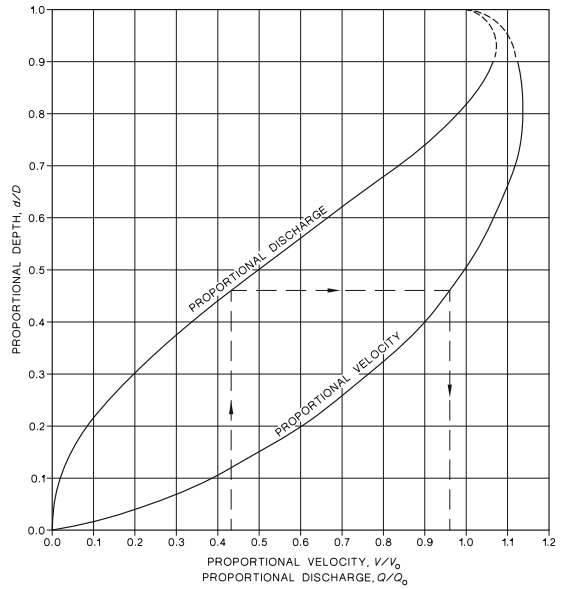
Use the chart below to find the actual velocity when flowing part full.
You know the proportional discharge, (your required flow compared to the 150 pipe full flow,) the chart will show you the proportional velocity compared to the 150 pipe full velocity, and the proportional depth.
Saves a lot of mucking around working backwards from the hydraulic radius.
If you haven't used this chart before, its interesting to note that both the maximum flow and the maximum velocity do not occur when the pipe is flowing full.
That is because for a circular pipe the maximum hydraulic radius does not occur when the pipe is full.
Hydraulic radius = Xsect Area / wetted perimeter.
-
Thank you all, especially Ben Tate
-
An interesting question and answers .
-
Dear Y. Choi,
I fully agree with the reply of Katalin Kiss and Peter Styles. We successfully apply Coolebrook-White in our hydraulic designs and simulations since almost 30 years now. When a sewer would be full of water with submerged in- and outlets then the slope of the sewer does not matter but only the difference in static head (in/out) and of course the sewer size, wall roughness and discrete losses at junctions, traps, ... In such cases gravity flow velocities in straight new HDPE or PP pipes may well exceed 3 m/s.
When a sewer or channel is not full and its outlet is free, then the flow is largely driven by the bottom slope (assuming no discontinuities). When this slope would be too steep, then the top layers of the water will "shoot" over the lower layers resulting in friction and turbulence with additional losses limiting the bulk liquid velocity. Using normal slopes we size for 1 - 2 m/s velocity at 100% design flow.
By the way, there is no 9.8 m/s or other velocity limit if there would be no friction (vacuum, zero wall losses). The velocity of a rain droplet is only limited by its friction in the air.
-
Formulae to determine the velocity of flow in a sewer or open channels were developed by researchers like Mannings by conducting experiments in the laboratories under constrained conditions. Actual flow conditions in a sewer may or may not match the conditions under which the experiments were conducted to derive the formula. The only way to determine the actual flow in a sewer is to install a flow meter on the sewer.
1 Comment
-
Mir, I fully agree with you.
One observation/addition with regard to the use of open channel flowmeters:
Some companies offer non contact down looking radars to measure surface velocity in open channels. In order to convert the measured velocity into a profiled, (average), velocity, they use an universal factor of 0.95. A dynamic factor should be used, due to the constantly varying ratio between the wetted cross section and the wetted perimeter in the stream, (especially in sewers).
The other option is to measure velocity with a contact Doppler sensor, which supposedly, sensed the echoes of al particles and bubbles dispersed in the liquid. Some flowing near the walls and others flowing closer to the center of the stream.
In addition, the location point of the sensor in a sewer is extremely important as well in order to get a reliable velocity measurement. Down looking radars do not let many choices since they have to be installed on top of the stream, in the manhole pit, just where the stream is mostly affected by the connection between the pipe and the manhole's concrete.
-
-
if the inlet is submerged. it is understood that the pipe always be full. i.e 100% full. you should take into consideration it.
-
Hi Yongseok Choi,
According to my experience, depending on Manning theory, the height of water flow in pipe is equal to 90% of the inside diameter of pipe. For actual calculation of velocity under gravity, your idea is right, the velocity of water flow inside sewer is always under 9.8 m/s. Attachment is for your reference that we had calculation and design in the actual condition.
-
Some other simple design principles for you to follow on this website http://www.thewatertreatments.com/wastewater-sewage-treatment/sewers-design-criteria/ but you may have local guidelines that you should consult.
-
There are heaps of free online calculators you can use, or you can make your own. Just Google 'free colebrook white', this is the first one that came up, and has an option for gravity or pressure systems. http://calculation.pipelife-documents.com/colebrook/
-
In an open channel flow (flow with a free surface) one can use Manning's equation if the flow can be assumed uniform (water surface slope parallel to the pipe slope, long pipe, no backwater effects...etc.). If the design condition is such that the pipe is full a full pipe flow equation should be used, which accounts for the head differential between the upstream and downstream sections of the pipe. Maximum allowable velocity through the pipe depend on the pipe materials the pipe is made of. My guess is 3 m/s limit is probably related to a concrete pipe where the velocity should not exceed about 9 to 10 ft/s (in the 3 m/s range). I hope this helps.
-
Dear Y Choi,
You asked a good question - however there is no one answer for your question. Whether the full flow or part flow is critical to your sewer network - depends on the design of your network. I attached a small Excel file with some of the calculations I used for both partial and full flow in the circular pipes (developed it at the time I was self studying the advanced hydraulics). The hydraulics plays a serious part in the sewer network design as well as provisions for maintenance (hydraulics deals with water - but there are a lot of objects in the sewers..). Regards, Iouri
-
Anyone using Manning is living in the past. The UK's Hydraulic Research Station published tables of pipe flows with different roughness factors using the Colebrook-White formula. This included how to deal with part full flow.
-
Dear Yonseok Choi,
You should introduce the hydraulic radius and/or hydraulic diameter to calculate the partial current instead of the full flow, where the water has free surface inside of the channel/pipe (e.g. Colebrook-White formula).
Here you can find a quite good description (see the part of the partially full pipe):
http://slideplayer.com/slide/6116180/
During the design it is important to hold the velocity around 1 m/s, because the friction loss is increase by velocity quadratically.